Mountaintop Marvel
BIG THINGS ARE happening
on the mountaintop.
Author: Mark Kanonik, PE

Photos: Todd Mason/Halkin Mason Photography
Each high-bay wing is a single-story space about 80 ft by 240 ft.

The completed C2 mixing box within the C2 high-bay.
South Mountain, just outside of Bethlehem, Pa., is the lofty home of Lehigh University’s Mountaintop Campus, a sprawling site that was once home to the research facility of Bethlehem Steel. Today, Lehigh University is reinventing the facility as a next-generation academic environment to support its Mountaintop Initiative, “a space in which students are given the freedom to pursue answers to open-ended questions while working in, and across, all disciplines,” according to the Initiative’s stated goals.
Rehabbing Building C
The first step in this reinvention involved the rehabilitation of Building C, a steel framed structure that was built in multiple phases from the late 1950s to the mid-1970s. In plan, Building C is shaped like the letter E, with three high-bay wings connected to a horizontally-curved “spine.” In its original usage, the high-bay wings housed light industrial spaces, and the spine housed offices, common areas and mechanical spaces. Each high-bay wing is a single-story space about 80 ft by 240 ft in plan, with a clear inside height of about 60 ft for overhead cranes. The spine is a three-story structure about 55 ft by 400 ft in plan. Interestingly, Building C is structurally separated into six buildings, with each of the three high-bay wings isolated from the spine, and the spine itself is separated into three sections.
Students have been using two of the three high-bays (and a small portion of the spine) for the past several years, turning the high-bays into open-air markets of ideas and collaborative spaces. Technically speaking, the City of Bethlehem considered usage of Building C to be temporary and subject to annual renewal. Lehigh wanted to permanently and prominently showcase these areas, so two-story additions dubbed “mixing boxes” were proposed as conference rooms within each high-bay. However, repurposing a nearly 60-year-old industrial building for use by students presented some challenges, particularly with respect to the Bethlehem Building Code, which is based on the 2009 International Building Code. The new program[1]ming would result in a change of occupancy of the high-bay wings from F-2 (low-hazard factory) to B (business), thus reclassifying the high-bay wings to a higher hazard category per Table 912.4 of the IBC.
This triggered a seismic analysis of the high-bays per Section 907.3.1 of 2009 IBC, even though no modifications to the existing structural framing were proposed, since the mixing boxes would be structurally isolated from the high-bays and, therefore, self-supporting. It should be no surprise that the steel framing of the high-bays is generally quite robust, given that the facility was designed by and built for one of the largest structural steel producers in the world at the time.
No Seismic but Plenty of Snow
Thankfully, Bethlehem is in an area of relatively low seismicity, and the high-bays can withstand the expected seismic loads as long as the mixing boxes do not add additional seismic load. The roof framing consists of open-web bar joists, and consideration of drifted snow loads was not included in the design of the lower por[1]tions of the roof. Given that the methodology to quantify drifted snow loads didn’t develop until decades after the building was designed and built, it was not unexpected that these low-roof areas were overstressed when considering drifted snow loads. The floor spaces under these low-roof areas were excluded from the project due to budget and programming constraints, but the design team felt that it was in Lehigh’s best interest to reinforce the low roofs as part of this work so that it can confidently repurpose these spaces in the future. The use and occupancy of the spine did not change with the new programming, and the proposed work resulted in only a very limited structural alteration. Therefore, it was not necessary to evaluate the spine to the same level as the high-bay wings.
The mixing boxes within both the C2 and C3 high-bays are two-story conference areas that allow students, faculty and guests sweeping and uninterrupted views of the student spaces across the entirety of the high-bay floors. A mixing box was also proposed for the C1 high-bay, and within this area is an essential electrical room that could not be impacted, although the space above the electrical room is valuable and useable. A mixing box could cantilever over the electrical room, thus capturing the space above without impacting existing utilities within the electrical room. Ultimately, the mixing box in the C1 high-bay was eliminated, but the design of the mixing boxes in the other high-bays initially had to be suitable for the C1 high-bay as well.
Floating Boxes
During the initial planning, a key requirement of the mixing boxes was that they could not interfere with the student spaces below, so the boxes appear to float above these spaces. A second yet equally important requirement was that the mixing boxes could not overpower the exposed industrial aesthetic of the high-bays. The original steel framing, particularly the columns, is exposed and integral to the original architectural design, so it was only natural that the mixing boxes would be framed of structural steel as well. A long cantilever over the electrical room might have been susceptible to vibrations from people walking throughout the conference rooms, and deep beams would be stiff enough to mitigate possible vibrations—but doing so would not satisfy the architectural design intent. Instead, a modified Warren truss was proposed to frame the mixing boxes.
While the truss originated as a structural response to the programming requirements, it quickly became a significant architectural feature. The diagonals are located “outside” of the mixing box to be clearly visible from the high-bay floor, all the while respecting the aesthetics of the high-bays, yet with a modern touch. A structure with a clean and logical flow of forces is always visually pleasing, and the diagonals and all exposed connections were fabricated to AISC AESS (architecturally exposed structural steel) Category 2 to create a minimalist look (see www.aisc.org/aess for more on the various categories). The window framing facing the high-bay runs the full height of the mixing box, so the truss is beyond the edge of the floor. The floor beams were detailed with an exposed knife-edge connection that bring the loads directly to the center line of the diagonals, eliminating eccentric loads and out-of-plane bending on the diagonals. Universal pin connectors (produced by Cast Connex) were used at each diagonal to further enhance the aesthetics of the truss.
Each mixing box is supported on 18-in.- diameter round hollow structural section (HSS) columns that were chosen over typical wide-flange columns because they have equal stiffness in both axes. The columns are founded on a 24-in.-thick mat foundation to limit the loads applied to the existing foundations. A beneficial consequence of a mat foundation was that the bases of the columns could be fixed rather than pinned, significantly reducing lateral drift and al[1]lowing somewhat more useable space per floor as the isolation joints could be smaller. When viewed from the floor of the high-bay spaces, the isolation joint around the mixing boxes is almost imperceptible.
Grand Entrance
Since Building C is the first building to be repurposed for the Mountaintop Initiative, it is fitting that the building has a grand entrance to welcome students and faculty. Located at the end of the spine near the C3 high-bay, the new entry also includes a conference room with an amazing view of the Lehigh Valley below. The existing columns in this area are very closely spaced and would detract from an open and inviting entrance, so a portion of the existing building was removed to permit a column-free space of roughly 40 ft by 25 ft in plan. Unlike the mixing boxes, the C3 entry is an exterior addition, meaning that it is subjected to wind loads as well as seismic loads. The structural layout of the addition is of sufficiently different lateral stiffness so as to necessitate isolating it from the rest of the building.
The entrance vestibule is bigger in plan than the conference room above, so some of the upper-level columns were transferred at the low roof to keep the entrance vestibule open and column free. The low roof of the entrance vestibule is also more than 2 ft lower in elevation than the floor of the conference room, so all of the beams (including the transfer beams supporting the upper level columns) were kinked to match both elevations.
Similar to the mixing boxes, the C3 entry is founded on a 24-in.-thick mat foundation. It also includes a new corridor that connects to the entire 400-ft length of the spine. For most of the corridor, the new roof framing is hung from the existing framing above. Near the entry, the corridor flares away from Building C, and the roof framing could not be hung from the existing building. As such, the framing is supported on slender 3-in.-diameter pipe columns aligned with the window mullions positioned to be as inconspicuous as possible.
Winds of Change
Renovating and expanding an existing building is always challenging. Design methodologies and assumptions change over time, as do materials and methods of construction. Even the amount of information shown on the drawings changes, and most buildings more than a few decades old were not designed for seismic and/or drifted snow loads. We were fortunate to have most of the original construction documents, but many of the utilities within the high-bays changed over time, and some were replaced about a year before this work began. We could not relocate utilities that were installed only a year earlier, even if they impeded the proposed work.
In hindsight, we should have contracted for a 3D laser survey of the inside of the high-bays; utilities would have been exactly located in each high-bay, and a few fit-up issues that were encountered during construction could have been avoided—something to consider for similar, future projects. In addition, erecting steel within an existing building is never easy, as the erector discovered when it took a full eight hours and two cranes to install the first column. That was a very steep learning curve, but after this, the rest of the steel erection went much more quickly.
The original building is approximately 120,000 gross sq. ft in area, and just over half of that area was renovated as part of this work. The two mixing boxes and the C3 entry added roughly 15,000 sq. ft of space framed with approximately 150 tons of new steel. From a structural perspective, Building C is now nine separate buildings under one roof, and together these nine buildings provide an exciting, attractive and adaptable space where Lehigh students are motivated to affect positive change in the world. ■
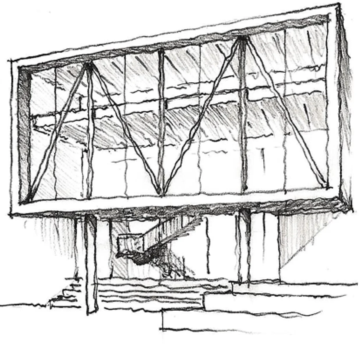
A sketch of the new space.

The “E” shape of the building.

AESS connection of a floor beam to a truss diagonal.

Detail views of an AESS floor-beam-to-truss-diagonal connection

Student spaces within the C2 high-bay.

Occupants “inside the box” can look out into the
high-bay space.

The project added 15,000 sq. ft of space to the existing 120,000-sq.-ft building.

Mark Kanonik (mkanonik@eypae.com)
is a senior associate and senior structural engineer with EYP Architecture and Engineering in Albany, N.Y. He is also an adjunct faculty member with Rensselaer Polytechnic Institute in Troy, N.Y., where he teaches a graduate-level course on steel and masonry.
AISC - Modern Steel - “Mountaintop Marvel”
NOVEMBER 2018
Photos: Todd Mason/Halkin Mason Photography
Link: mountaintopmarvel.pdf